Camera Calibration and 3D Reconstruction
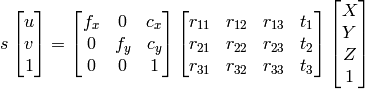
The functions in this section use the so-called pinhole camera model. That is, a scene view is formed by projecting 3D points into the image plane using a perspective transformation.
![s \; m' = A [R|t] M'](_images/math/765aba62c7cb09fd36c1b44f3a2e422a28c4ec70.png)
or
Where
 are the coordinates of a 3D point in the world
coordinate space,
are the coordinates of a 3D point in the world
coordinate space,
 are the coordinates of the projection point
in pixels.
are the coordinates of the projection point
in pixels.
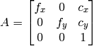
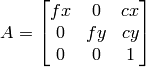
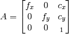
 is called a camera matrix, or a matrix of
intrinsic parameters.
is called a camera matrix, or a matrix of
intrinsic parameters.
 is a principal point (that is
usually at the image center), and
is a principal point (that is
usually at the image center), and
 are the focal lengths
expressed in pixel-related units. Thus, if an image from camera is
scaled by some factor, all of these parameters should
be scaled (multiplied/divided, respectively) by the same factor. The
matrix of intrinsic parameters does not depend on the scene viewed and,
once estimated, can be re-used (as long as the focal length is fixed (in
case of zoom lens)). The joint rotation-translation matrix
are the focal lengths
expressed in pixel-related units. Thus, if an image from camera is
scaled by some factor, all of these parameters should
be scaled (multiplied/divided, respectively) by the same factor. The
matrix of intrinsic parameters does not depend on the scene viewed and,
once estimated, can be re-used (as long as the focal length is fixed (in
case of zoom lens)). The joint rotation-translation matrix
![[R|t]](_images/math/2ec354f9c8316cb3d69be8ceb97c53180a29640e.png) is called a matrix of extrinsic parameters. It is used to describe the
camera motion around a static scene, or vice versa, rigid motion of an
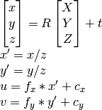
object in front of still camera. That is,
translates
coordinates of a point
to some coordinate system,
fixed with respect to the camera. The transformation above is equivalent
to the following (when
is called a matrix of extrinsic parameters. It is used to describe the
camera motion around a static scene, or vice versa, rigid motion of an
object in front of still camera. That is,
translates
coordinates of a point
to some coordinate system,
fixed with respect to the camera. The transformation above is equivalent
to the following (when
 ):
):
Real lenses usually have some distortion, mostly radial distortion and slight tangential distortion. So, the above model is extended as:
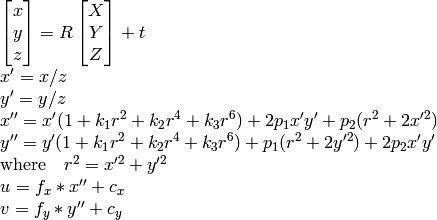
 ,
,
 ,
,
 are radial distortion coefficients,
 ,
,
 are tangential distortion coefficients.
Higher-order coefficients are not considered in OpenCV. In the functions below the coefficients are passed or returned as
are tangential distortion coefficients.
Higher-order coefficients are not considered in OpenCV. In the functions below the coefficients are passed or returned as
![(k_1, k_2, p_1, p_2[, k_3])](_images/math/4972eec50bbe577c72b5d258e682495024072d5f.png)
vector. That is, if the vector contains 4 elements, it means that
 .
The distortion coefficients do not depend on the scene viewed, thus they also belong to the intrinsic camera parameters.
And they remain the same regardless of the captured image resolution.
That is, if, for example, a camera has been calibrated on images of
.
The distortion coefficients do not depend on the scene viewed, thus they also belong to the intrinsic camera parameters.
And they remain the same regardless of the captured image resolution.
That is, if, for example, a camera has been calibrated on images of
 resolution, absolutely the same distortion coefficients can
be used for images of
resolution, absolutely the same distortion coefficients can
be used for images of
 resolution from the same camera (while
 ,
,
 ,
,
 and
and
 need to be scaled appropriately).
The functions below use the above model to
- Project 3D points to the image plane given intrinsic and extrinsic parameters
- Compute extrinsic parameters given intrinsic parameters, a few 3D points and their projections.
- Estimate intrinsic and extrinsic camera parameters from several views of a known calibration pattern (i.e. every view is described by several 3D-2D point correspondences).
- Estimate the relative position and orientation of the stereo camera “heads” and compute the rectification transformation that makes the camera optical axes parallel.
CalcImageHomography
- void cvCalcImageHomography(float* line, CvPoint3D32f* center, float* intrinsic, float* homography)
Calculates the homography matrix for an oblong planar object (e.g. arm).
Parameters: - line – the main object axis direction (vector (dx,dy,dz))
- center – object center ((cx,cy,cz))
- intrinsic – intrinsic camera parameters (3x3 matrix)
- homography – output homography matrix (3x3)
The function calculates the homography matrix for the initial image transformation from image plane to the plane, defined by a 3D oblong object line (See _ _ Figure 6-10 _ _ in the OpenCV Guide 3D Reconstruction Chapter).
CalibrateCamera2
- double cvCalibrateCamera2(const CvMat* objectPoints, const CvMat* imagePoints, const CvMat* pointCounts, CvSize imageSize, CvMat* cameraMatrix, CvMat* distCoeffs, CvMat* rvecs=NULL, CvMat* tvecs=NULL, int flags=0)
Finds the camera intrinsic and extrinsic parameters from several views of a calibration pattern.
Parameters: - objectPoints – The joint matrix of object points - calibration pattern features in the model coordinate space. It is floating-point 3xN or Nx3 1-channel, or 1xN or Nx1 3-channel array, where N is the total number of points in all views.
- imagePoints – The joint matrix of object points projections in the camera views. It is floating-point 2xN or Nx2 1-channel, or 1xN or Nx1 2-channel array, where N is the total number of points in all views
- pointCounts – Integer 1xM or Mx1 vector (where M is the number of calibration pattern views) containing the number of points in each particular view. The sum of vector elements must match the size of objectPoints and imagePoints (=N).
- imageSize – Size of the image, used only to initialize the intrinsic camera matrix
- cameraMatrix – The output 3x3 floating-point camera matrix
 . If CV_CALIB_USE_INTRINSIC_GUESS and/or CV_CALIB_FIX_ASPECT_RATIO are specified, some or all of fx, fy, cx, cy must be initialized before calling the function
 - distCoeffs – The output 4x1, 1x4, 5x1 or 1x5 vector of distortion coefficients
![(k_1, k_2, p_1, p_2[, k_3])](_images/math/00139c2d6590850e2b07264b39d783c0839b7337.png)
.
Parameters: - rvecs – The output 3x M or M x3 1-channel, or 1x M or M x1 3-channel array of rotation vectors (see Rodrigues2 ), estimated for each pattern view. That is, each k-th rotation vector together with the corresponding k-th translation vector (see the next output parameter description) brings the calibration pattern from the model coordinate space (in which object points are specified) to the world coordinate space, i.e. real position of the calibration pattern in the k-th pattern view (k=0.. M -1)
- tvecs – The output 3x M or M x3 1-channel, or 1x M or M x1 3-channel array of translation vectors, estimated for each pattern view.
- flags –
Different flags, may be 0 or combination of the following values:
- CV_CALIB_USE_INTRINSIC_GUESS cameraMatrix contains the valid initial values of fx, fy, cx, cy that are optimized further. Otherwise, (cx, cy) is initially set to the image center ( imageSize is used here), and focal distances are computed in some least-squares fashion. Note, that if intrinsic parameters are known, there is no need to use this function just to estimate the extrinsic parameters. Use FindExtrinsicCameraParams2 instead.
- CV_CALIB_FIX_PRINCIPAL_POINT The principal point is not changed during the global optimization, it stays at the center or at the other location specified when CV_CALIB_USE_INTRINSIC_GUESS is set too.
- CV_CALIB_FIX_ASPECT_RATIO The functions considers only fy as a free parameter, the ratio fx/fy stays the same as in the input cameraMatrix . When CV_CALIB_USE_INTRINSIC_GUESS is not set, the actual input values of fx and fy are ignored, only their ratio is computed and used further.
- CV_CALIB_ZERO_TANGENT_DIST Tangential distortion coefficients
 will be set to zeros and stay zero.
The function estimates the intrinsic camera parameters and extrinsic parameters for each of the views. The coordinates of 3D object points and their correspondent 2D projections in each view must be specified. That may be achieved by using an object with known geometry and easily detectable feature points. Such an object is called a calibration rig or calibration pattern, and OpenCV has built-in support for a chessboard as a calibration rig (see FindChessboardCorners ). Currently, initialization of intrinsic parameters (when CV_CALIB_USE_INTRINSIC_GUESS is not set) is only implemented for planar calibration patterns (where z-coordinates of the object points must be all 0’s). 3D calibration rigs can also be used as long as initial cameraMatrix is provided.
The algorithm does the following:
- First, it computes the initial intrinsic parameters (the option only available for planar calibration patterns) or reads them from the input parameters. The distortion coefficients are all set to zeros initially (unless some of CV_CALIB_FIX_K? are specified).
- The initial camera pose is estimated as if the intrinsic parameters have been already known. This is done using FindExtrinsicCameraParams2
- After that the global Levenberg-Marquardt optimization algorithm is run to minimize the reprojection error, i.e. the total sum of squared distances between the observed feature points imagePoints and the projected (using the current estimates for camera parameters and the poses) object points objectPoints ; see ProjectPoints2 .
The function returns the final re-projection error.
Note: if you’re using a non-square (=non-NxN) grid and
findChessboardCorners()
for calibration, and
calibrateCamera
returns
bad values (i.e. zero distortion coefficients, an image center very far from
 , and / or large differences between
and
(ratios of
10:1 or more)), then you’ve probably used
patternSize=cvSize(rows,cols)
,
but should use
patternSize=cvSize(cols,rows)
in
FindChessboardCorners
.
, and / or large differences between
and
(ratios of
10:1 or more)), then you’ve probably used
patternSize=cvSize(rows,cols)
,
but should use
patternSize=cvSize(cols,rows)
in
FindChessboardCorners
.
See also: FindChessboardCorners , FindExtrinsicCameraParams2 , initCameraMatrix2D() , StereoCalibrate , Undistort2
ComputeCorrespondEpilines
- void cvComputeCorrespondEpilines(const CvMat* points, int whichImage, const CvMat* F, CvMat* lines)
For points in one image of a stereo pair, computes the corresponding epilines in the other image.
Parameters: - points – The input points. 2xN, Nx2, 3xN or Nx3 array (where N number of points). Multi-channel 1xN or Nx1 array is also acceptable
- whichImage – Index of the image (1 or 2) that contains the points
- F – The fundamental matrix that can be estimated using FindFundamentalMat or StereoRectify .
- lines – The output epilines, a 3xN or Nx3 array. Each line
 is encoded by 3 numbers
For every point in one of the two images of a stereo-pair the function finds the equation of the corresponding epipolar line in the other image.
From the fundamental matrix definition (see
FindFundamentalMat
),
line
 in the second image for the point
 in the first image (i.e. when
whichImage=1
) is computed as:
in the first image (i.e. when
whichImage=1
) is computed as:

and, vice versa, when
whichImage=2
,
 is computed from
 as:
as:

Line coefficients are defined up to a scale. They are normalized, such that
 .
.
ConvertPointsHomogeneous
- void cvConvertPointsHomogeneous(const CvMat* src, CvMat* dst)
Convert points to/from homogeneous coordinates.
Parameters: - src – The input point array, 2xN, Nx2, 3xN, Nx3, 4xN or Nx4 (where ``N is the number of points)`` . Multi-channel 1xN or Nx1 array is also acceptable
- dst – The output point array, must contain the same number of points as the input; The dimensionality must be the same, 1 less or 1 more than the input, and also within 2 to 4
The function converts 2D or 3D points from/to homogeneous coordinates, or simply copies or transposes the array. If the input array dimensionality is larger than the output, each coordinate is divided by the last coordinate:
![\begin{array}{l} (x,y[,z],w) -> (x',y'[,z']) \\ \text{where} \\ x' = x/w \\ y' = y/w \\ z' = z/w \quad \text{(if output is 3D)} \end{array}](_images/math/8da5c69bcb6b6386781ae5cdcd555ed70460e785.png)
If the output array dimensionality is larger, an extra 1 is appended to each point. Otherwise, the input array is simply copied (with optional transposition) to the output.
Note because the function accepts a large variety of array layouts, it may report an error when input/output array dimensionality is ambiguous. It is always safe to use the function with number of points  , or to use multi-channel Nx1 or 1xN arrays.
CreatePOSITObject
- CvPOSITObject* cvCreatePOSITObject(CvPoint3D32f* points, int point_count)
Initializes a structure containing object information.
Parameters: - points – Pointer to the points of the 3D object model
- point_count – Number of object points
The function allocates memory for the object structure and computes the object inverse matrix.
The preprocessed object data is stored in the structure CvPOSITObject , internal for OpenCV, which means that the user cannot directly access the structure data. The user may only create this structure and pass its pointer to the function.
An object is defined as a set of points given in a coordinate system. The function POSIT computes a vector that begins at a camera-related coordinate system center and ends at the points[0] of the object.
Once the work with a given object is finished, the function ReleasePOSITObject must be called to free memory.
CreateStereoBMState
- CvStereoBMState* cvCreateStereoBMState(int preset=CV_STEREO_BM_BASIC, int numberOfDisparities=0)
Creates block matching stereo correspondence structure.
Parameters: - preset –
ID of one of the pre-defined parameter sets. Any of the parameters can be overridden after creating the structure. Values are
- CV_STEREO_BM_BASIC Parameters suitable for general cameras
- CV_STEREO_BM_FISH_EYE Parameters suitable for wide-angle cameras
- CV_STEREO_BM_NARROW Parameters suitable for narrow-angle cameras
- numberOfDisparities – The number of disparities. If the parameter is 0, it is taken from the preset, otherwise the supplied value overrides the one from preset.
- preset –
The function creates the stereo correspondence structure and initializes it. It is possible to override any of the parameters at any time between the calls to FindStereoCorrespondenceBM .
CreateStereoGCState
- CvStereoGCState* cvCreateStereoGCState(int numberOfDisparities, int maxIters)
Creates the state of graph cut-based stereo correspondence algorithm.
Parameters: - numberOfDisparities – The number of disparities. The disparity search range will be

- maxIters – Maximum number of iterations. On each iteration all possible (or reasonable) alpha-expansions are tried. The algorithm may terminate earlier if it could not find an alpha-expansion that decreases the overall cost function value. See [Kolmogorov03] for details.
- numberOfDisparities – The number of disparities. The disparity search range will be
The function creates the stereo correspondence structure and initializes it. It is possible to override any of the parameters at any time between the calls to FindStereoCorrespondenceGC .
CvStereoBMState
- CvStereoBMState
The structure for block matching stereo correspondence algorithm.
typedef struct CvStereoBMState
{
    //pre filters (normalize input images):
    int       preFilterType; // 0 for now
    int       preFilterSize; // ~5x5..21x21
    int       preFilterCap;  // up to ~31
    //correspondence using Sum of Absolute Difference (SAD):
    int       SADWindowSize; // Could be 5x5..21x21
    int       minDisparity;  // minimum disparity (=0)
    int       numberOfDisparities; // maximum disparity - minimum disparity
    //post filters (knock out bad matches):
    int       textureThreshold; // areas with no texture are ignored
    int       uniquenessRatio;// invalidate disparity at pixels where there are other close matches
                              // with different disparity
    int       speckleWindowSize; // the maximum area of speckles to remove
                                 // (set to 0 to disable speckle filtering)
    int       speckleRange; // acceptable range of disparity variation in each connected component

    int trySmallerWindows; // not used
    CvRect roi1, roi2; // clipping ROIs

    int disp12MaxDiff; // maximum allowed disparity difference in the left-right check

    // internal data
    ...
}
CvStereoBMState;
- preFilterType
- type of the prefilter, CV_STEREO_BM_NORMALIZED_RESPONSE or the default and the recommended CV_STEREO_BM_XSOBEL , int
- preFilterSize
- ~5x5..21x21, int
- preFilterCap
- up to ~31, int
- SADWindowSize
- Could be 5x5..21x21 or higher, but with 21x21 or smaller windows the processing speed is much higher, int
- minDisparity
- minimum disparity (=0), int
- numberOfDisparities
- maximum disparity - minimum disparity, int
- textureThreshold
- the textureness threshold. That is, if the sum of absolute values of x-derivatives computed over SADWindowSize by SADWindowSize pixel neighborhood is smaller than the parameter, no disparity is computed at the pixel, int
- uniquenessRatio
- the minimum margin in percents between the best (minimum) cost function value and the second best value to accept the computed disparity, int
- speckleWindowSize
- the maximum area of speckles to remove (set to 0 to disable speckle filtering), int
- speckleRange
- acceptable range of disparity variation in each connected component, int
- trySmallerWindows
- not used currently (0), int
- roi1, roi2
- These are the clipping ROIs for the left and the right images. The function StereoRectify returns the largest rectangles in the left and right images where after the rectification all the pixels are valid. If you copy those rectangles to the CvStereoBMState structure, the stereo correspondence function will automatically clear out the pixels outside of the “valid” disparity rectangle computed by GetValidDisparityROI . Thus you will get more “invalid disparity” pixels than usual, but the remaining pixels are more probable to be valid.
- disp12MaxDiff
- The maximum allowed difference between the explicitly computed left-to-right disparity map and the implicitly (by ValidateDisparity ) computed right-to-left disparity. If for some pixel the difference is larger than the specified threshold, the disparity at the pixel is invalidated. By default this parameter is set to (-1), which means that the left-right check is not performed.
The block matching stereo correspondence algorithm, by Kurt Konolige, is very fast single-pass stereo matching algorithm that uses sliding sums of absolute differences between pixels in the left image and the pixels in the right image, shifted by some varying amount of pixels (from minDisparity to minDisparity+numberOfDisparities ). On a pair of images WxH the algorithm computes disparity in O(W*H*numberOfDisparities) time. In order to improve quality and readability of the disparity map, the algorithm includes pre-filtering and post-filtering procedures.
Note that the algorithm searches for the corresponding blocks in x direction only. It means that the supplied stereo pair should be rectified. Vertical stereo layout is not directly supported, but in such a case the images could be transposed by user.
CvStereoGCState
- CvStereoGCState
The structure for graph cuts-based stereo correspondence algorithm
typedef struct CvStereoGCState
{
    int Ithreshold; // threshold for piece-wise linear data cost function (5 by default)
    int interactionRadius; // radius for smoothness cost function (1 by default; means Potts model)
    float K, lambda, lambda1, lambda2; // parameters for the cost function
                                       // (usually computed adaptively from the input data)
    int occlusionCost; // 10000 by default
    int minDisparity; // 0 by default; see CvStereoBMState
    int numberOfDisparities; // defined by user; see CvStereoBMState
    int maxIters; // number of iterations; defined by user.

    // internal buffers
    CvMat* left;
    CvMat* right;
    CvMat* dispLeft;
    CvMat* dispRight;
    CvMat* ptrLeft;
    CvMat* ptrRight;
    CvMat* vtxBuf;
    CvMat* edgeBuf;
}
CvStereoGCState;
The graph cuts stereo correspondence algorithm, described in [Kolmogorov03] (as KZ1 ), is non-realtime stereo correspondence algorithm that usually gives very accurate depth map with well-defined object boundaries. The algorithm represents stereo problem as a sequence of binary optimization problems, each of those is solved using maximum graph flow algorithm. The state structure above should not be allocated and initialized manually; instead, use CreateStereoGCState and then override necessary parameters if needed.
DecomposeProjectionMatrix
- void cvDecomposeProjectionMatrix(const CvMat *projMatrix, CvMat *cameraMatrix, CvMat *rotMatrix, CvMat *transVect, CvMat *rotMatrX=NULL, CvMat *rotMatrY=NULL, CvMat *rotMatrZ=NULL, CvPoint3D64f *eulerAngles=NULL)
Decomposes the projection matrix into a rotation matrix and a camera matrix.
Parameters: - projMatrix – The 3x4 input projection matrix P
- cameraMatrix – The output 3x3 camera matrix K
- rotMatrix – The output 3x3 external rotation matrix R
- transVect – The output 4x1 translation vector T
- rotMatrX – Optional 3x3 rotation matrix around x-axis
- rotMatrY – Optional 3x3 rotation matrix around y-axis
- rotMatrZ – Optional 3x3 rotation matrix around z-axis
- eulerAngles – Optional 3 points containing the three Euler angles of rotation
The function computes a decomposition of a projection matrix into a calibration and a rotation matrix and the position of the camera.
It optionally returns three rotation matrices, one for each axis, and the three Euler angles that could be used in OpenGL.
The function is based on RQDecomp3x3 .
DrawChessboardCorners
- void cvDrawChessboardCorners(CvArr* image, CvSize patternSize, CvPoint2D32f* corners, int count, int patternWasFound)
Renders the detected chessboard corners.
Parameters: - image – The destination image; it must be an 8-bit color image
- patternSize – The number of inner corners per chessboard row and column. (patternSize = cvSize(points _ per _ row,points _ per _ colum) = cvSize(columns,rows) )
- corners – The array of corners detected
- count – The number of corners
- patternWasFound – Indicates whether the complete board was found
 or not
  . One may just pass the return value FindChessboardCorners here
The function draws the individual chessboard corners detected as red circles if the board was not found or as colored corners connected with lines if the board was found.
FindChessboardCorners
- int cvFindChessboardCorners(const void* image, CvSize patternSize, CvPoint2D32f* corners, int* cornerCount=NULL, int flags=CV_CALIB_CB_ADAPTIVE_THRESH)
Finds the positions of the internal corners of the chessboard.
Parameters: - image – Source chessboard view; it must be an 8-bit grayscale or color image
- patternSize – The number of inner corners per chessboard row and column ( patternSize = cvSize(points _ per _ row,points _ per _ colum) = cvSize(columns,rows) )
- corners – The output array of corners detected
- cornerCount – The output corner counter. If it is not NULL, it stores the number of corners found
- flags –
Various operation flags, can be 0 or a combination of the following values:
- CV_CALIB_CB_ADAPTIVE_THRESH use adaptive thresholding to convert the image to black and white, rather than a fixed threshold level (computed from the average image brightness).
- CV_CALIB_CB_NORMALIZE_IMAGE normalize the image gamma with EqualizeHist before applying fixed or adaptive thresholding.
- CV_CALIB_CB_FILTER_QUADS use additional criteria (like contour area, perimeter, square-like shape) to filter out false quads that are extracted at the contour retrieval stage.
The function attempts to determine whether the input image is a view of the chessboard pattern and locate the internal chessboard corners. The function returns a non-zero value if all of the corners have been found and they have been placed in a certain order (row by row, left to right in every row), otherwise, if the function fails to find all the corners or reorder them, it returns 0. For example, a regular chessboard has 8 x 8 squares and 7 x 7 internal corners, that is, points, where the black squares touch each other. The coordinates detected are approximate, and to determine their position more accurately, the user may use the function FindCornerSubPix .
Note: the function requires some white space (like a square-thick border, the wider the better) around the board to make the detection more robust in various environment (otherwise if there is no border and the background is dark, the outer black squares could not be segmented properly and so the square grouping and ordering algorithm will fail).
FindExtrinsicCameraParams2
- void cvFindExtrinsicCameraParams2(const CvMat* objectPoints, const CvMat* imagePoints, const CvMat* cameraMatrix, const CvMat* distCoeffs, CvMat* rvec, CvMat* tvec, int useExtrinsicGuess=0)
Finds the object pose from the 3D-2D point correspondences
Parameters: - objectPoints – The array of object points in the object coordinate space, 3xN or Nx3 1-channel, or 1xN or Nx1 3-channel, where N is the number of points.
- imagePoints – The array of corresponding image points, 2xN or Nx2 1-channel or 1xN or Nx1 2-channel, where N is the number of points.
- cameraMatrix – The input camera matrix
- distCoeffs – The input 4x1, 1x4, 5x1 or 1x5 vector of distortion coefficients . If it is NULL, all of the distortion coefficients are set to 0
- rvec – The output rotation vector (see Rodrigues2 ) that (together with tvec ) brings points from the model coordinate system to the camera coordinate system
- tvec – The output translation vector
- useExtrinsicGuess – If true (1), the function will use the provided rvec and tvec as the initial approximations of the rotation and translation vectors, respectively, and will further optimize them.
The function estimates the object pose given a set of object points, their corresponding image projections, as well as the camera matrix and the distortion coefficients. This function finds such a pose that minimizes reprojection error, i.e. the sum of squared distances between the observed projections imagePoints and the projected (using ProjectPoints2 ) objectPoints .
FindFundamentalMat
- int cvFindFundamentalMat(const CvMat* points1, const CvMat* points2, CvMat* fundamentalMatrix, int method=CV_FM_RANSAC, double param1=1., double param2=0.99, CvMat* status=NULL)
Calculates the fundamental matrix from the corresponding points in two images.
Parameters: - points1 – Array of N points from the first image. It can be 2xN, Nx2, 3xN or Nx3 1-channel array or 1xN or Nx1 2- or 3-channel array . The point coordinates should be floating-point (single or double precision)
- points2 – Array of the second image points of the same size and format as points1
- fundamentalMatrix – The output fundamental matrix or matrices. The size should be 3x3 or 9x3 (7-point method may return up to 3 matrices)
- method –
Method for computing the fundamental matrix
- CV_FM_7POINT for a 7-point algorithm.

- CV_FM_8POINT for an 8-point algorithm.

- CV_FM_RANSAC for the RANSAC algorithm.
- CV_FM_LMEDS for the LMedS algorithm.
- CV_FM_7POINT for a 7-point algorithm.
- param1 – The parameter is used for RANSAC. It is the maximum distance from point to epipolar line in pixels, beyond which the point is considered an outlier and is not used for computing the final fundamental matrix. It can be set to something like 1-3, depending on the accuracy of the point localization, image resolution and the image noise
- param2 – The parameter is used for RANSAC or LMedS methods only. It specifies the desirable level of confidence (probability) that the estimated matrix is correct
- status – The optional output array of N elements, every element of which is set to 0 for outliers and to 1 for the other points. The array is computed only in RANSAC and LMedS methods. For other methods it is set to all 1’s
The epipolar geometry is described by the following equation:
![[p_2; 1]^T F [p_1; 1] = 0](_images/math/0ba9438e14e73a4bac80f18d7aa26cb1c2531543.png)
where
 is fundamental matrix,
and
are corresponding points in the first and the second images, respectively.
is fundamental matrix,
and
are corresponding points in the first and the second images, respectively.
The function calculates the fundamental matrix using one of four methods listed above and returns
the number of fundamental matrices found (1 or 3) and 0, if no matrix is found
. Normally just 1 matrix is found, but in the case of 7-point algorithm the function may return up to 3 solutions (
 matrix that stores all 3 matrices sequentially).
The calculated fundamental matrix may be passed further to ComputeCorrespondEpilines that finds the epipolar lines corresponding to the specified points. It can also be passed to StereoRectifyUncalibrated to compute the rectification transformation.
int point_count = 100;
CvMat* points1;
CvMat* points2;
CvMat* status;
CvMat* fundamental_matrix;

points1 = cvCreateMat(1,point_count,CV_32FC2);
points2 = cvCreateMat(1,point_count,CV_32FC2);
status = cvCreateMat(1,point_count,CV_8UC1);

/* Fill the points here ... */
for( i = 0; i < point_count; i++ )
{
    points1->data.fl[i*2] = <x,,1,i,,>;
    points1->data.fl[i*2+1] = <y,,1,i,,>;
    points2->data.fl[i*2] = <x,,2,i,,>;
    points2->data.fl[i*2+1] = <y,,2,i,,>;
}

fundamental_matrix = cvCreateMat(3,3,CV_32FC1);
int fm_count = cvFindFundamentalMat( points1,points2,fundamental_matrix,
                                     CV_FM_RANSAC,1.0,0.99,status );
FindHomography
- void cvFindHomography(const CvMat* srcPoints, const CvMat* dstPoints, CvMat* H int method=0, double ransacReprojThreshold=0, CvMat* status=NULL)
Finds the perspective transformation between two planes.
Parameters: - srcPoints – Coordinates of the points in the original plane, 2xN, Nx2, 3xN or Nx3 1-channel array (the latter two are for representation in homogeneous coordinates), where N is the number of points. 1xN or Nx1 2- or 3-channel array can also be passed.
- dstPoints – Point coordinates in the destination plane, 2xN, Nx2, 3xN or Nx3 1-channel, or 1xN or Nx1 2- or 3-channel array.
- H – The output 3x3 homography matrix
- method –
The method used to computed homography matrix; one of the following:
- 0 a regular method using all the points
- CV_RANSAC RANSAC-based robust method
- CV_LMEDS Least-Median robust method
- ransacReprojThreshold –
The maximum allowed reprojection error to treat a point pair as an inlier (used in the RANSAC method only). That is, if

then the point
 is considered an outlier. If srcPoints and dstPoints are measured in pixels, it usually makes sense to set this parameter somewhere in the range 1 to 10.
 - status – The optional output mask set by a robust method ( CV_RANSAC or CV_LMEDS ). Note that the input mask values are ignored.
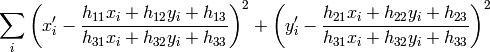
The
function finds
the perspective transformation
 between the source and the destination planes:
So that the back-projection error
is minimized. If the parameter method is set to the default value 0, the function uses all the point pairs to compute the initial homography estimate with a simple least-squares scheme.
However, if not all of the point pairs (
 ,
,
 ) fit the rigid perspective transformation (i.e. there
are some outliers), this initial estimate will be poor.
In this case one can use one of the 2 robust methods. Both methods,
RANSAC
and
LMeDS
, try many different random subsets
of the corresponding point pairs (of 4 pairs each), estimate
the homography matrix using this subset and a simple least-square
algorithm and then compute the quality/goodness of the computed homography
(which is the number of inliers for RANSAC or the median re-projection
error for LMeDs). The best subset is then used to produce the initial
estimate of the homography matrix and the mask of inliers/outliers.
) fit the rigid perspective transformation (i.e. there
are some outliers), this initial estimate will be poor.
In this case one can use one of the 2 robust methods. Both methods,
RANSAC
and
LMeDS
, try many different random subsets
of the corresponding point pairs (of 4 pairs each), estimate
the homography matrix using this subset and a simple least-square
algorithm and then compute the quality/goodness of the computed homography
(which is the number of inliers for RANSAC or the median re-projection
error for LMeDs). The best subset is then used to produce the initial
estimate of the homography matrix and the mask of inliers/outliers.
Regardless of the method, robust or not, the computed homography matrix is refined further (using inliers only in the case of a robust method) with the Levenberg-Marquardt method in order to reduce the re-projection error even more.
The method RANSAC can handle practically any ratio of outliers, but it needs the threshold to distinguish inliers from outliers. The method LMeDS does not need any threshold, but it works correctly only when there are more than 50 % of inliers. Finally, if you are sure in the computed features, where can be only some small noise present, but no outliers, the default method could be the best choice.
The function is used to find initial intrinsic and extrinsic matrices.
Homography matrix is determined up to a scale, thus it is normalized so that
 .
.
See also: GetAffineTransform , GetPerspectiveTransform , EstimateRigidMotion , WarpPerspective , PerspectiveTransform
FindStereoCorrespondenceBM
- void cvFindStereoCorrespondenceBM(const CvArr* left, const CvArr* right, CvArr* disparity, CvStereoBMState* state)
Computes the disparity map using block matching algorithm.
Parameters: - left – The left single-channel, 8-bit image.
- right – The right image of the same size and the same type.
- disparity – The output single-channel 16-bit signed, or 32-bit floating-point disparity map of the same size as input images. In the first case the computed disparities are represented as fixed-point numbers with 4 fractional bits (i.e. the computed disparity values are multiplied by 16 and rounded to integers).
- state – Stereo correspondence structure.
The function cvFindStereoCorrespondenceBM computes disparity map for the input rectified stereo pair. Invalid pixels (for which disparity can not be computed) are set to state->minDisparity - 1 (or to (state->minDisparity-1)*16 in the case of 16-bit fixed-point disparity map)
FindStereoCorrespondenceGC
- void cvFindStereoCorrespondenceGC(const CvArr* left, const CvArr* right, CvArr* dispLeft, CvArr* dispRight, CvStereoGCState* state, int useDisparityGuess = CV_DEFAULT(0))
Computes the disparity map using graph cut-based algorithm.
Parameters: - left – The left single-channel, 8-bit image.
- right – The right image of the same size and the same type.
- dispLeft – The optional output single-channel 16-bit signed left disparity map of the same size as input images.
- dispRight – The optional output single-channel 16-bit signed right disparity map of the same size as input images.
- state – Stereo correspondence structure.
- useDisparityGuess – If the parameter is not zero, the algorithm will start with pre-defined disparity maps. Both dispLeft and dispRight should be valid disparity maps. Otherwise, the function starts with blank disparity maps (all pixels are marked as occlusions).
The function computes disparity maps for the input rectified stereo pair. Note that the left disparity image will contain values in the following range:

or

and for the right disparity image the following will be true:

or

that is, the range for the left disparity image will be inversed, and the pixels for which no good match has been found, will be marked as occlusions.
Here is how the function can be used:
// image_left and image_right are the input 8-bit single-channel images
// from the left and the right cameras, respectively
CvSize size = cvGetSize(image_left);
CvMat* disparity_left = cvCreateMat( size.height, size.width, CV_16S );
CvMat* disparity_right = cvCreateMat( size.height, size.width, CV_16S );
CvStereoGCState* state = cvCreateStereoGCState( 16, 2 );
cvFindStereoCorrespondenceGC( image_left, image_right,
    disparity_left, disparity_right, state, 0 );
cvReleaseStereoGCState( &state );
// now process the computed disparity images as you want ...
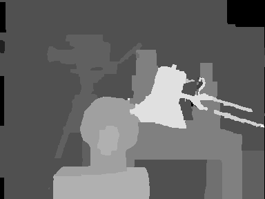
and this is the output left disparity image computed from the well-known Tsukuba stereo pair and multiplied by -16 (because the values in the left disparity images are usually negative):
CvMat* disparity_left_visual = cvCreateMat( size.height, size.width, CV_8U );
cvConvertScale( disparity_left, disparity_left_visual, -16 );
cvSave( "disparity.pgm", disparity_left_visual );
GetOptimalNewCameraMatrix
- void cvGetOptimalNewCameraMatrix(const CvMat* cameraMatrix, const CvMat* distCoeffs, CvSize imageSize, double alpha, CvMat* newCameraMatrix, CvSize newImageSize=cvSize(0, 0), CvRect* validPixROI=0)
Returns the new camera matrix based on the free scaling parameter
Parameters: - cameraMatrix – The input camera matrix
- distCoeffs – The input 4x1, 1x4, 5x1 or 1x5 vector of distortion coefficients
.
Parameters: - imageSize – The original image size
- alpha – The free scaling parameter between 0 (when all the pixels in the undistorted image will be valid) and 1 (when all the source image pixels will be retained in the undistorted image); see StereoRectify
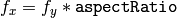
- newCameraMatrix – The output new camera matrix.
- newImageSize – The image size after rectification. By default it will be set to imageSize .
- validPixROI – The optional output rectangle that will outline all-good-pixels region in the undistorted image. See roi1, roi2 description in StereoRectify
The function computes the optimal new camera matrix based on the free scaling parameter. By varying this parameter the user may retrieve only sensible pixels alpha=0 , keep all the original image pixels if there is valuable information in the corners alpha=1 , or get something in between. When alpha>0 , the undistortion result will likely have some black pixels corresponding to “virtual” pixels outside of the captured distorted image. The original camera matrix, distortion coefficients, the computed new camera matrix and the newImageSize should be passed to InitUndistortRectifyMap to produce the maps for Remap .
InitIntrinsicParams2D
- void cvInitIntrinsicParams2D(const CvMat* objectPoints, const CvMat* imagePoints, const CvMat* npoints, CvSize imageSize, CvMat* cameraMatrix, double aspectRatio=1.)
Finds the initial camera matrix from the 3D-2D point correspondences
Parameters: - objectPoints – The joint array of object points; see CalibrateCamera2
- imagePoints – The joint array of object point projections; see CalibrateCamera2
- npoints – The array of point counts; see CalibrateCamera2
- imageSize – The image size in pixels; used to initialize the principal point
- cameraMatrix – The output camera matrix

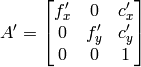
- aspectRatio – If it is zero or negative, both and are estimated independently. Otherwise
The function estimates and returns the initial camera matrix for camera calibration process. Currently, the function only supports planar calibration patterns, i.e. patterns where each object point has z-coordinate =0.
InitUndistortMap
- void cvInitUndistortMap(const CvMat* cameraMatrix, const CvMat* distCoeffs, CvArr* map1, CvArr* map2)
Computes an undistortion map.
Parameters: - cameraMatrix – The input camera matrix
- distCoeffs – The input 4x1, 1x4, 5x1 or 1x5 vector of distortion coefficients
.
Parameters: - map1 – The first output map of type CV_32FC1 or CV_16SC2 - the second variant is more efficient
- map2 – The second output map of type CV_32FC1 or CV_16UC1 - the second variant is more efficient
- cameraMatrix – The input camera matrix
The function is a simplified variant of InitUndistortRectifyMap where the rectification transformation R is identity matrix and newCameraMatrix=cameraMatrix .
InitUndistortRectifyMap
- void cvInitUndistortRectifyMap(const CvMat* cameraMatrix, const CvMat* distCoeffs, const CvMat* R, const CvMat* newCameraMatrix, CvArr* map1, CvArr* map2)
Computes the undistortion and rectification transformation map.
Parameters: - cameraMatrix – The input camera matrix

- distCoeffs – The input 4x1, 1x4, 5x1 or 1x5 vector of distortion coefficients
.
Parameters: - R – The optional rectification transformation in object space (3x3 matrix). R1 or R2 , computed by StereoRectify can be passed here. If the matrix is NULL , the identity transformation is assumed
- newCameraMatrix – The new camera matrix
- map1 – The first output map of type CV_32FC1 or CV_16SC2 - the second variant is more efficient
- map2 – The second output map of type CV_32FC1 or CV_16UC1 - the second variant is more efficient
- cameraMatrix – The input camera matrix
The function computes the joint undistortion+rectification transformation and represents the result in the form of maps for Remap . The undistorted image will look like the original, as if it was captured with a camera with camera matrix =newCameraMatrix and zero distortion. In the case of monocular camera newCameraMatrix is usually equal to cameraMatrix , or it can be computed by GetOptimalNewCameraMatrix for a better control over scaling. In the case of stereo camera newCameraMatrix is normally set to P1 or P2 computed by StereoRectify .
Also, this new camera will be oriented differently in the coordinate space, according to R . That, for example, helps to align two heads of a stereo camera so that the epipolar lines on both images become horizontal and have the same y- coordinate (in the case of horizontally aligned stereo camera).
The function actually builds the maps for the inverse mapping algorithm that is used by
Remap
. That is, for each pixel
in the destination (corrected and rectified) image the function computes the corresponding coordinates in the source image (i.e. in the original image from camera). The process is the following:
![\begin{array}{l} x \leftarrow (u - {c'}_x)/{f'}_x \\ y \leftarrow (v - {c'}_y)/{f'}_y \\{[X\,Y\,W]} ^T \leftarrow R^{-1}*[x \, y \, 1]^T \\ x' \leftarrow X/W \\ y' \leftarrow Y/W \\ x" \leftarrow x' (1 + k_1 r^2 + k_2 r^4 + k_3 r^6) + 2p_1 x' y' + p_2(r^2 + 2 x'^2) \\ y" \leftarrow y' (1 + k_1 r^2 + k_2 r^4 + k_3 r^6) + p_1 (r^2 + 2 y'^2) + 2 p_2 x' y' \\ map_x(u,v) \leftarrow x" f_x + c_x \\ map_y(u,v) \leftarrow y" f_y + c_y \end{array}](_images/math/b2ef04e09ac8e397d10674839524575bbc2ffb3e.png)
where
are the distortion coefficients.
In the case of a stereo camera this function is called twice, once for each camera head, after StereoRectify , which in its turn is called after StereoCalibrate . But if the stereo camera was not calibrated, it is still possible to compute the rectification transformations directly from the fundamental matrix using StereoRectifyUncalibrated . For each camera the function computes homography H as the rectification transformation in pixel domain, not a rotation matrix R in 3D space. The R can be computed from H as

where the cameraMatrix can be chosen arbitrarily.
POSIT
- void cvPOSIT(CvPOSITObject* posit_object, CvPoint2D32f* imagePoints, double focal_length, CvTermCriteria criteria, CvMatr32f rotationMatrix, CvVect32f translation_vector)
Implements the POSIT algorithm.
Parameters: - posit_object – Pointer to the object structure
- imagePoints – Pointer to the object points projections on the 2D image plane
- focal_length – Focal length of the camera used
- criteria – Termination criteria of the iterative POSIT algorithm
- rotationMatrix – Matrix of rotations
- translation_vector – Translation vector
The function implements the POSIT algorithm. Image coordinates are given in a camera-related coordinate system. The focal length may be retrieved using the camera calibration functions. At every iteration of the algorithm a new perspective projection of the estimated pose is computed.
Difference norm between two projections is the maximal distance between corresponding points. The parameter criteria.epsilon serves to stop the algorithm if the difference is small.
ProjectPoints2
- void cvProjectPoints2(const CvMat* objectPoints, const CvMat* rvec, const CvMat* tvec, const CvMat* cameraMatrix, const CvMat* distCoeffs, CvMat* imagePoints, CvMat* dpdrot=NULL, CvMat* dpdt=NULL, CvMat* dpdf=NULL, CvMat* dpdc=NULL, CvMat* dpddist=NULL)
Project 3D points on to an image plane.
Parameters: - objectPoints – The array of object points, 3xN or Nx3 1-channel or 1xN or Nx1 3-channel , where N is the number of points in the view
- rvec – The rotation vector, see Rodrigues2
- tvec – The translation vector
- cameraMatrix – The camera matrix
- distCoeffs – The input 4x1, 1x4, 5x1 or 1x5 vector of distortion coefficients . If it is NULL , all of the distortion coefficients are considered 0’s
- imagePoints – The output array of image points, 2xN or Nx2 1-channel or 1xN or Nx1 2-channel
- dpdrot – Optional 2Nx3 matrix of derivatives of image points with respect to components of the rotation vector
- dpdt – Optional 2Nx3 matrix of derivatives of image points with respect to components of the translation vector
- dpdf – Optional 2Nx2 matrix of derivatives of image points with respect to and
- dpdc – Optional 2Nx2 matrix of derivatives of image points with respect to and
- dpddist – Optional 2Nx4 matrix of derivatives of image points with respect to distortion coefficients
The function computes projections of 3D points to the image plane given intrinsic and extrinsic camera parameters. Optionally, the function computes jacobians - matrices of partial derivatives of image points coordinates (as functions of all the input parameters) with respect to the particular parameters, intrinsic and/or extrinsic. The jacobians are used during the global optimization in CalibrateCamera2 , FindExtrinsicCameraParams2 and StereoCalibrate . The function itself can also used to compute re-projection error given the current intrinsic and extrinsic parameters.
Note, that by setting rvec=tvec=(0,0,0) , or by setting cameraMatrix to 3x3 identity matrix, or by passing zero distortion coefficients, you can get various useful partial cases of the function, i.e. you can compute the distorted coordinates for a sparse set of points, or apply a perspective transformation (and also compute the derivatives) in the ideal zero-distortion setup etc.
ReprojectImageTo3D
- void cvReprojectImageTo3D(const CvArr* disparity, CvArr* _3dImage, const CvMat* Q, int handleMissingValues=0)
Reprojects disparity image to 3D space.
Parameters: - disparity – The input single-channel 16-bit signed or 32-bit floating-point disparity image
- _3dImage – The output 3-channel floating-point image of the same size as disparity . Each element of _3dImage(x,y) will contain the 3D coordinates of the point (x,y) , computed from the disparity map.
- Q – The
 perspective transformation matrix that can be obtained with StereoRectify
 - handleMissingValues – If true, when the pixels with the minimal disparity (that corresponds to the outliers; see FindStereoCorrespondenceBM ) will be transformed to 3D points with some very large Z value (currently set to 10000)
The function transforms 1-channel disparity map to 3-channel image representing a 3D surface. That is, for each pixel (x,y) and the corresponding disparity d=disparity(x,y) it computes:
![\begin{array}{l} [X \; Y \; Z \; W]^T = \texttt{Q} *[x \; y \; \texttt{disparity} (x,y) \; 1]^T \\ \texttt{\_3dImage} (x,y) = (X/W, \; Y/W, \; Z/W) \end{array}](_images/math/1af29654ff7bcec951f0d0adb80aadf62672fde5.png)
The matrix
Q
can be arbitrary
matrix, e.g. the one computed by
StereoRectify
. To reproject a sparse set of points {(x,y,d),...} to 3D space, use
PerspectiveTransform
.
RQDecomp3x3
- void cvRQDecomp3x3(const CvMat *M, CvMat *R, CvMat *Q, CvMat *Qx=NULL, CvMat *Qy=NULL, CvMat *Qz=NULL, CvPoint3D64f *eulerAngles=NULL)
Computes the ‘RQ’ decomposition of 3x3 matrices.
Parameters: - M – The 3x3 input matrix
- R – The output 3x3 upper-triangular matrix
- Q – The output 3x3 orthogonal matrix
- Qx – Optional 3x3 rotation matrix around x-axis
- Qy – Optional 3x3 rotation matrix around y-axis
- Qz – Optional 3x3 rotation matrix around z-axis
- eulerAngles – Optional three Euler angles of rotation
The function computes a RQ decomposition using the given rotations. This function is used in DecomposeProjectionMatrix to decompose the left 3x3 submatrix of a projection matrix into a camera and a rotation matrix.
It optionally returns three rotation matrices, one for each axis, and the three Euler angles that could be used in OpenGL.
ReleasePOSITObject
- void cvReleasePOSITObject(CvPOSITObject** posit_object)
Deallocates a 3D object structure.
Parameter: posit_object – Double pointer to CvPOSIT structure
The function releases memory previously allocated by the function CreatePOSITObject .
ReleaseStereoBMState
- void cvReleaseStereoBMState(CvStereoBMState** state)
Releases block matching stereo correspondence structure.
Parameter: state – Double pointer to the released structure.
The function releases the stereo correspondence structure and all the associated internal buffers.
ReleaseStereoGCState
- void cvReleaseStereoGCState(CvStereoGCState** state)
Releases the state structure of the graph cut-based stereo correspondence algorithm.
Parameter: state – Double pointer to the released structure.
The function releases the stereo correspondence structure and all the associated internal buffers.
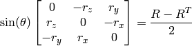
Rodrigues2
- int cvRodrigues2(const CvMat* src, CvMat* dst, CvMat* jacobian=0)
Converts a rotation matrix to a rotation vector or vice versa.
Parameters: - src – The input rotation vector (3x1 or 1x3) or rotation matrix (3x3)
- dst – The output rotation matrix (3x3) or rotation vector (3x1 or 1x3), respectively
- jacobian – Optional output Jacobian matrix, 3x9 or 9x3 - partial derivatives of the output array components with respect to the input array components
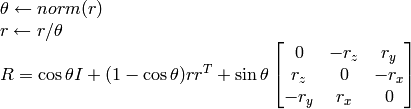
Inverse transformation can also be done easily, since
A rotation vector is a convenient and most-compact representation of a rotation matrix (since any rotation matrix has just 3 degrees of freedom). The representation is used in the global 3D geometry optimization procedures like CalibrateCamera2 , StereoCalibrate or FindExtrinsicCameraParams2 .
StereoCalibrate
- double cvStereoCalibrate(const CvMat* objectPoints, const CvMat* imagePoints1, const CvMat* imagePoints2, const CvMat* pointCounts, CvMat* cameraMatrix1, CvMat* distCoeffs1, CvMat* cameraMatrix2, CvMat* distCoeffs2, CvSize imageSize, CvMat* R, CvMat* T, CvMat* E=0, CvMat* F=0, CvTermCriteria term_crit=cvTermCriteria( CV_TERMCRIT_ITER+CV_TERMCRIT_EPS, 30, 1e-6), int flags=CV_CALIB_FIX_INTRINSIC)
Calibrates stereo camera.
Parameters: - objectPoints – The joint matrix of object points - calibration pattern features in the model coordinate space. It is floating-point 3xN or Nx3 1-channel, or 1xN or Nx1 3-channel array, where N is the total number of points in all views.
- imagePoints1 – The joint matrix of object points projections in the first camera views. It is floating-point 2xN or Nx2 1-channel, or 1xN or Nx1 2-channel array, where N is the total number of points in all views
- imagePoints2 – The joint matrix of object points projections in the second camera views. It is floating-point 2xN or Nx2 1-channel, or 1xN or Nx1 2-channel array, where N is the total number of points in all views
- pointCounts – Integer 1xM or Mx1 vector (where M is the number of calibration pattern views) containing the number of points in each particular view. The sum of vector elements must match the size of objectPoints and imagePoints* (=N).
- cameraMatrix1 – The input/output first camera matrix:
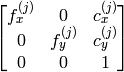 ,
,  . If any of CV_CALIB_USE_INTRINSIC_GUESS , CV_CALIB_FIX_ASPECT_RATIO , CV_CALIB_FIX_INTRINSIC or CV_CALIB_FIX_FOCAL_LENGTH are specified, some or all of the matrices’ components must be initialized; see the flags description
 - distCoeffs1 – The input/output lens distortion coefficients for the first camera, 4x1, 5x1, 1x4 or 1x5 floating-point vectors
![(k_1^{(j)}, k_2^{(j)}, p_1^{(j)}, p_2^{(j)}[, k_3^{(j)}])](_images/math/9341350d35c0b33716d8d9e4b5d811b700402f08.png) , . If any of CV_CALIB_FIX_K1 , CV_CALIB_FIX_K2 or CV_CALIB_FIX_K3 is specified, then the corresponding elements of the distortion coefficients must be initialized.
, . If any of CV_CALIB_FIX_K1 , CV_CALIB_FIX_K2 or CV_CALIB_FIX_K3 is specified, then the corresponding elements of the distortion coefficients must be initialized. - cameraMatrix2 – The input/output second camera matrix, as cameraMatrix1.
- distCoeffs2 – The input/output lens distortion coefficients for the second camera, as distCoeffs1.
- imageSize – Size of the image, used only to initialize intrinsic camera matrix.
- R – The output rotation matrix between the 1st and the 2nd cameras’ coordinate systems.
- T – The output translation vector between the cameras’ coordinate systems.
- E – The optional output essential matrix.
- F – The optional output fundamental matrix.
- term_crit – The termination criteria for the iterative optimization algorithm.
- flags –
Different flags, may be 0 or combination of the following values:
- CV_CALIB_FIX_INTRINSIC If it is set, cameraMatrix? , as well as distCoeffs? are fixed, so that only R, T, E and F are estimated.
- CV_CALIB_USE_INTRINSIC_GUESS The flag allows the function to optimize some or all of the intrinsic parameters, depending on the other flags, but the initial values are provided by the user.
- CV_CALIB_FIX_PRINCIPAL_POINT The principal points are fixed during the optimization.
- CV_CALIB_FIX_FOCAL_LENGTH
 and
and  are fixed.
 - CV_CALIB_FIX_ASPECT_RATIO is optimized, but the ratio
 is fixed.
 - CV_CALIB_SAME_FOCAL_LENGTH Enforces
 and
and 
- CV_CALIB_ZERO_TANGENT_DIST Tangential distortion coefficients for each camera are set to zeros and fixed there.
- CV_CALIB_FIX_K1, CV_CALIB_FIX_K2, CV_CALIB_FIX_K3 Fixes the corresponding radial distortion coefficient (the coefficient must be passed to the function)
The function estimates transformation between the 2 cameras making a stereo pair. If we have a stereo camera, where the relative position and orientation of the 2 cameras is fixed, and if we computed poses of an object relative to the fist camera and to the second camera, (R1, T1) and (R2, T2), respectively (that can be done with
FindExtrinsicCameraParams2
), obviously, those poses will relate to each other, i.e. given (
 ,
,
 ) it should be possible to compute (
 ,
,
 ) - we only need to know the position and orientation of the 2nd camera relative to the 1st camera. That’s what the described function does. It computes (
 ,
,
 ) such that:

Optionally, it computes the essential matrix E:
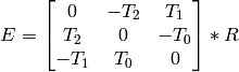
where
 are components of the translation vector
:
are components of the translation vector
:
![T=[T_0, T_1, T_2]^T](_images/math/586c8ad76bed1689a0d7d3cf8356439559b1d4de.png) . And also the function can compute the fundamental matrix F:
. And also the function can compute the fundamental matrix F:

Besides the stereo-related information, the function can also perform full calibration of each of the 2 cameras. However, because of the high dimensionality of the parameter space and noise in the input data the function can diverge from the correct solution. Thus, if intrinsic parameters can be estimated with high accuracy for each of the cameras individually (e.g. using CalibrateCamera2 ), it is recommended to do so and then pass CV_CALIB_FIX_INTRINSIC flag to the function along with the computed intrinsic parameters. Otherwise, if all the parameters are estimated at once, it makes sense to restrict some parameters, e.g. pass CV_CALIB_SAME_FOCAL_LENGTH and CV_CALIB_ZERO_TANGENT_DIST flags, which are usually reasonable assumptions.
Similarly to CalibrateCamera2 , the function minimizes the total re-projection error for all the points in all the available views from both cameras. The function returns the final value of the re-projection error.
StereoRectify
- void cvStereoRectify(const CvMat* cameraMatrix1, const CvMat* cameraMatrix2, const CvMat* distCoeffs1, const CvMat* distCoeffs2, CvSize imageSize, const CvMat* R, const CvMat* T, CvMat* R1, CvMat* R2, CvMat* P1, CvMat* P2, CvMat* Q=0, int flags=CV_CALIB_ZERO_DISPARITY, double alpha=-1, CvSize newImageSize=cvSize(0, 0), CvRect* roi1=0, CvRect* roi2=0)
Computes rectification transforms for each head of a calibrated stereo camera.
Parameters: - cameraMatrix1, cameraMatrix2 – The camera matrices .
- distCoeffs1, distCoeffs2 – The input distortion coefficients for each camera,
![{k_1}^{(j)}, {k_2}^{(j)}, {p_1}^{(j)}, {p_2}^{(j)} [, {k_3}^{(j)}]](_images/math/41ee0aa33912371d07818a29062d2d1acc24b645.png)
- imageSize – Size of the image used for stereo calibration.
- R – The rotation matrix between the 1st and the 2nd cameras’ coordinate systems.
- T – The translation vector between the cameras’ coordinate systems.
- R1, R2 – The output
 rectification transforms (rotation matrices) for the first and the second cameras, respectively.
 - P1, P2 – The output
 projection matrices in the new (rectified) coordinate systems.
 - Q – The output disparity-to-depth mapping matrix, see reprojectImageTo3D() .
- flags – The operation flags; may be 0 or CV_CALIB_ZERO_DISPARITY . If the flag is set, the function makes the principal points of each camera have the same pixel coordinates in the rectified views. And if the flag is not set, the function may still shift the images in horizontal or vertical direction (depending on the orientation of epipolar lines) in order to maximize the useful image area.
- alpha – The free scaling parameter. If it is -1 , the functions performs some default scaling. Otherwise the parameter should be between 0 and 1. alpha=0 means that the rectified images will be zoomed and shifted so that only valid pixels are visible (i.e. there will be no black areas after rectification). alpha=1 means that the rectified image will be decimated and shifted so that all the pixels from the original images from the cameras are retained in the rectified images, i.e. no source image pixels are lost. Obviously, any intermediate value yields some intermediate result between those two extreme cases.
- newImageSize – The new image resolution after rectification. The same size should be passed to InitUndistortRectifyMap , see the stereo_calib.cpp sample in OpenCV samples directory. By default, i.e. when (0,0) is passed, it is set to the original imageSize . Setting it to larger value can help you to preserve details in the original image, especially when there is big radial distortion.
- roi1, roi2 – The optional output rectangles inside the rectified images where all the pixels are valid. If alpha=0 , the ROIs will cover the whole images, otherwise they likely be smaller, see the picture below
- cameraMatrix1, cameraMatrix2 – The camera matrices
The function computes the rotation matrices for each camera that (virtually) make both camera image planes the same plane. Consequently, that makes all the epipolar lines parallel and thus simplifies the dense stereo correspondence problem. On input the function takes the matrices computed by stereoCalibrate() and on output it gives 2 rotation matrices and also 2 projection matrices in the new coordinates. The 2 cases are distinguished by the function are:
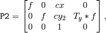
Horizontal stereo, when 1st and 2nd camera views are shifted relative to each other mainly along the x axis (with possible small vertical shift). Then in the rectified images the corresponding epipolar lines in left and right cameras will be horizontal and have the same y-coordinate. P1 and P2 will look as:
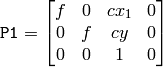
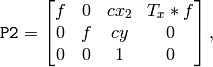
where
 is horizontal shift between the cameras and
 if
CV_CALIB_ZERO_DISPARITY
is set.
if
CV_CALIB_ZERO_DISPARITY
is set.Vertical stereo, when 1st and 2nd camera views are shifted relative to each other mainly in vertical direction (and probably a bit in the horizontal direction too). Then the epipolar lines in the rectified images will be vertical and have the same x coordinate. P2 and P2 will look as:
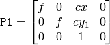
where
 is vertical shift between the cameras and
 if
CALIB_ZERO_DISPARITY
is set.
if
CALIB_ZERO_DISPARITY
is set.
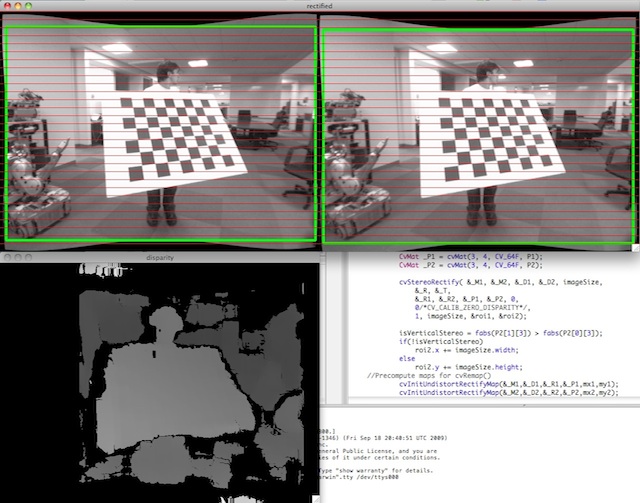
As you can see, the first 3 columns of P1 and P2 will effectively be the new “rectified” camera matrices. The matrices, together with R1 and R2 , can then be passed to InitUndistortRectifyMap to initialize the rectification map for each camera.
Below is the screenshot from stereo_calib.cpp sample. Some red horizontal lines, as you can see, pass through the corresponding image regions, i.e. the images are well rectified (which is what most stereo correspondence algorithms rely on). The green rectangles are roi1 and roi2 - indeed, their interior are all valid pixels.
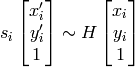
StereoRectifyUncalibrated
- void cvStereoRectifyUncalibrated(const CvMat* points1, const CvMat* points2, const CvMat* F, CvSize imageSize, CvMat* H1, CvMat* H2, double threshold=5)
Computes rectification transform for uncalibrated stereo camera.
Parameters: - points1, points2 – The 2 arrays of corresponding 2D points. The same formats as in FindFundamentalMat are supported
- F – The input fundamental matrix. It can be computed from the same set of point pairs using FindFundamentalMat .
- imageSize – Size of the image.
- H1, H2 – The output rectification homography matrices for the first and for the second images.
- threshold – The optional threshold used to filter out the outliers. If the parameter is greater than zero, then all the point pairs that do not comply the epipolar geometry well enough (that is, the points for which
![|\texttt{points2[i]}^T*\texttt{F}*\texttt{points1[i]}|>\texttt{threshold}](_images/math/e77a03eb53f034dff5b0581485e41f7339b205bf.png) ) are rejected prior to computing the homographies.
Otherwise all the points are considered inliers.
) are rejected prior to computing the homographies.
Otherwise all the points are considered inliers.
The function computes the rectification transformations without knowing intrinsic parameters of the cameras and their relative position in space, hence the suffix “Uncalibrated”. Another related difference from StereoRectify is that the function outputs not the rectification transformations in the object (3D) space, but the planar perspective transformations, encoded by the homography matrices H1 and H2 . The function implements the algorithm [Hartley99] .
Note that while the algorithm does not need to know the intrinsic parameters of the cameras, it heavily depends on the epipolar geometry. Therefore, if the camera lenses have significant distortion, it would better be corrected before computing the fundamental matrix and calling this function. For example, distortion coefficients can be estimated for each head of stereo camera separately by using CalibrateCamera2 and then the images can be corrected using Undistort2 , or just the point coordinates can be corrected with UndistortPoints .
Undistort2
- void cvUndistort2(const CvArr* src, CvArr* dst, const CvMat* cameraMatrix, const CvMat* distCoeffs, const CvMat* newCameraMatrix=0)
Transforms an image to compensate for lens distortion.
Parameters: - src – The input (distorted) image
- dst – The output (corrected) image; will have the same size and the same type as src
- cameraMatrix – The input camera matrix
- distCoeffs – The vector of distortion coefficients,
The function transforms the image to compensate radial and tangential lens distortion.
The function is simply a combination of InitUndistortRectifyMap (with unity R ) and Remap (with bilinear interpolation). See the former function for details of the transformation being performed.
Those pixels in the destination image, for which there is no correspondent pixels in the source image, are filled with 0’s (black color).
The particular subset of the source image that will be visible in the corrected image can be regulated by newCameraMatrix . You can use GetOptimalNewCameraMatrix to compute the appropriate newCameraMatrix , depending on your requirements.
The camera matrix and the distortion parameters can be determined using
CalibrateCamera2
. If the resolution of images is different from the used at the calibration stage,
 and
need to be scaled accordingly, while the distortion coefficients remain the same.
and
need to be scaled accordingly, while the distortion coefficients remain the same.
UndistortPoints
- void cvUndistortPoints(const CvMat* src, CvMat* dst, const CvMat* cameraMatrix, const CvMat* distCoeffs, const CvMat* R=NULL, const CvMat* P=NULL)
Computes the ideal point coordinates from the observed point coordinates.
Parameters: - src – The observed point coordinates, same format as imagePoints in ProjectPoints2
- dst – The output ideal point coordinates, after undistortion and reverse perspective transformation , same format as src .
- cameraMatrix – The camera matrix
- distCoeffs – The vector of distortion coefficients,
- R – The rectification transformation in object space (3x3 matrix). R1 or R2 , computed by StereoRectify() can be passed here. If the matrix is empty, the identity transformation is used
- P – The new camera matrix (3x3) or the new projection matrix (3x4). P1 or P2 , computed by StereoRectify() can be passed here. If the matrix is empty, the identity new camera matrix is used
The function is similar to Undistort2 and InitUndistortRectifyMap , but it operates on a sparse set of points instead of a raster image. Also the function does some kind of reverse transformation to ProjectPoints2 (in the case of 3D object it will not reconstruct its 3D coordinates, of course; but for a planar object it will, up to a translation vector, if the proper R is specified).
// (u,v) is the input point, (u', v') is the output point
// camera_matrix=[fx 0 cx; 0 fy cy; 0 0 1]
// P=[fx' 0 cx' tx; 0 fy' cy' ty; 0 0 1 tz]
x" = (u - cx)/fx
y" = (v - cy)/fy
(x',y') = undistort(x",y",dist_coeffs)
[X,Y,W]T = R*[x' y' 1]T
x = X/W, y = Y/W
u' = x*fx' + cx'
v' = y*fy' + cy',
where undistort() is approximate iterative algorithm that estimates the normalized original point coordinates out of the normalized distorted point coordinates (“normalized” means that the coordinates do not depend on the camera matrix).
The function can be used both for a stereo camera head or for monocular camera (when R is NULL ).
Help and Feedback
You did not find what you were looking for?- Try the FAQ.
- Ask a question in the user group/mailing list.
- If you think something is missing or wrong in the documentation, please file a bug report.
![]()
Table Of Contents
- Camera Calibration and 3D Reconstruction
- CalcImageHomography
- CalibrateCamera2
- ComputeCorrespondEpilines
- ConvertPointsHomogeneous
- CreatePOSITObject
- CreateStereoBMState
- CreateStereoGCState
- CvStereoBMState
- CvStereoGCState
- DecomposeProjectionMatrix
- DrawChessboardCorners
- FindChessboardCorners
- FindExtrinsicCameraParams2
- FindFundamentalMat
- FindHomography
- FindStereoCorrespondenceBM
- FindStereoCorrespondenceGC
- GetOptimalNewCameraMatrix
- InitIntrinsicParams2D
- InitUndistortMap
- InitUndistortRectifyMap
- POSIT
- ProjectPoints2
- ReprojectImageTo3D
- RQDecomp3x3
- ReleasePOSITObject
- ReleaseStereoBMState
- ReleaseStereoGCState
- Rodrigues2
- StereoCalibrate
- StereoRectify
- StereoRectifyUncalibrated
- Undistort2
- UndistortPoints
Previous topic
Next topic
highgui. High-level GUI and Media IO