Geometric Image Transformations
The functions in this section perform various geometrical transformations of 2D images. That is, they do not change the image content, but deform the pixel grid, and map this deformed grid to the destination image. In fact, to avoid sampling artifacts, the mapping is done in the reverse order, from destination to the source. That is, for each pixel
 of the destination image, the functions compute coordinates of the corresponding “donor” pixel in the source image and copy the pixel value, that is:

In the case when the user specifies the forward mapping:
 , the OpenCV functions first compute the corresponding inverse mapping:
 and then use the above formula.
The actual implementations of the geometrical transformations, from the most generic Remap and to the simplest and the fastest Resize , need to solve the 2 main problems with the above formula:
- extrapolation of non-existing pixels. Similarly to the filtering functions, described in the previous section, for some
 one of
 or
or
 , or they both, may fall outside of the image, in which case some extrapolation method needs to be used. OpenCV provides the same selection of the extrapolation methods as in the filtering functions, but also an additional method
BORDER_TRANSPARENT
, which means that the corresponding pixels in the destination image will not be modified at all.
, or they both, may fall outside of the image, in which case some extrapolation method needs to be used. OpenCV provides the same selection of the extrapolation methods as in the filtering functions, but also an additional method
BORDER_TRANSPARENT
, which means that the corresponding pixels in the destination image will not be modified at all. - interpolation of pixel values. Usually
and
are floating-point numbers (i.e.
 can be an affine or perspective transformation, or radial lens distortion correction etc.), so a pixel values at fractional coordinates needs to be retrieved. In the simplest case the coordinates can be just rounded to the nearest integer coordinates and the corresponding pixel used, which is called nearest-neighbor interpolation. However, a better result can be achieved by using more sophisticated
interpolation methods
, where a polynomial function is fit into some neighborhood of the computed pixel
can be an affine or perspective transformation, or radial lens distortion correction etc.), so a pixel values at fractional coordinates needs to be retrieved. In the simplest case the coordinates can be just rounded to the nearest integer coordinates and the corresponding pixel used, which is called nearest-neighbor interpolation. However, a better result can be achieved by using more sophisticated
interpolation methods
, where a polynomial function is fit into some neighborhood of the computed pixel
 and then the value of the polynomial at
is taken as the interpolated pixel value. In OpenCV you can choose between several interpolation methods, see
Resize
.
and then the value of the polynomial at
is taken as the interpolated pixel value. In OpenCV you can choose between several interpolation methods, see
Resize
.
GetRotationMatrix2D
- CvMat* cv2DRotationMatrix(CvPoint2D32f center, double angle, double scale, CvMat* mapMatrix)
Calculates the affine matrix of 2d rotation.
Parameters: - center – Center of the rotation in the source image
- angle – The rotation angle in degrees. Positive values mean counter-clockwise rotation (the coordinate origin is assumed to be the top-left corner)
- scale – Isotropic scale factor
- mapMatrix – Pointer to the destination
 matrix
The function cv2DRotationMatrix calculates the following matrix:
where

The transformation maps the rotation center to itself. If this is not the purpose, the shift should be adjusted.
GetAffineTransform
- CvMat* cvGetAffineTransform(const CvPoint2D32f* src, const CvPoint2D32f* dst, CvMat* mapMatrix)
Calculates the affine transform from 3 corresponding points.
Parameters: - src – Coordinates of 3 triangle vertices in the source image
- dst – Coordinates of the 3 corresponding triangle vertices in the destination image
- mapMatrix – Pointer to the destination
 matrix
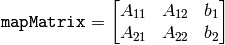
The function cvGetAffineTransform calculates the matrix of an affine transform such that:
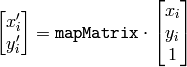
where

GetPerspectiveTransform
- CvMat* cvGetPerspectiveTransform(const CvPoint2D32f* src, const CvPoint2D32f* dst, CvMat* mapMatrix)
Calculates the perspective transform from 4 corresponding points.
Parameters: - src – Coordinates of 4 quadrangle vertices in the source image
- dst – Coordinates of the 4 corresponding quadrangle vertices in the destination image
- mapMatrix – Pointer to the destination
 matrix
The function cvGetPerspectiveTransform calculates a matrix of perspective transforms such that:
where

GetQuadrangleSubPix
- void cvGetQuadrangleSubPix(const CvArr* src, CvArr* dst, const CvMat* mapMatrix)
Retrieves the pixel quadrangle from an image with sub-pixel accuracy.
Parameters: - src – Source image
- dst – Extracted quadrangle
- mapMatrix – The transformation matrix
![[A|b]](_images/math/5811dc4a2ff4e426ab272d1d4da6988db5790e51.png) (see the discussion)
(see the discussion)
The function cvGetQuadrangleSubPix extracts pixels from src at sub-pixel accuracy and stores them to dst as follows:

where

and
The values of pixels at non-integer coordinates are retrieved using bilinear interpolation. When the function needs pixels outside of the image, it uses replication border mode to reconstruct the values. Every channel of multiple-channel images is processed independently.
GetRectSubPix
- void cvGetRectSubPix(const CvArr* src, CvArr* dst, CvPoint2D32f center)
Retrieves the pixel rectangle from an image with sub-pixel accuracy.
Parameters: - src – Source image
- dst – Extracted rectangle
- center – Floating point coordinates of the extracted rectangle center within the source image. The center must be inside the image
The function cvGetRectSubPix extracts pixels from src :

where the values of the pixels at non-integer coordinates are retrieved using bilinear interpolation. Every channel of multiple-channel images is processed independently. While the rectangle center must be inside the image, parts of the rectangle may be outside. In this case, the replication border mode is used to get pixel values beyond the image boundaries.
LogPolar
- void cvLogPolar(const CvArr* src, CvArr* dst, CvPoint2D32f center, double M, int flags=CV_INTER_LINEAR+CV_WARP_FILL_OUTLIERS)
Remaps an image to log-polar space.
Parameters: - src – Source image
- dst – Destination image
- center – The transformation center; where the output precision is maximal
- M – Magnitude scale parameter. See below
- flags –
A combination of interpolation methods and the following optional flags:
- CV_WARP_FILL_OUTLIERS fills all of the destination image pixels. If some of them correspond to outliers in the source image, they are set to zero
- CV_WARP_INVERSE_MAP See below
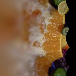
The function cvLogPolar transforms the source image using the following transformation:
Forward transformation ( CV_WARP_INVERSE_MAP is not set):
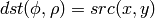
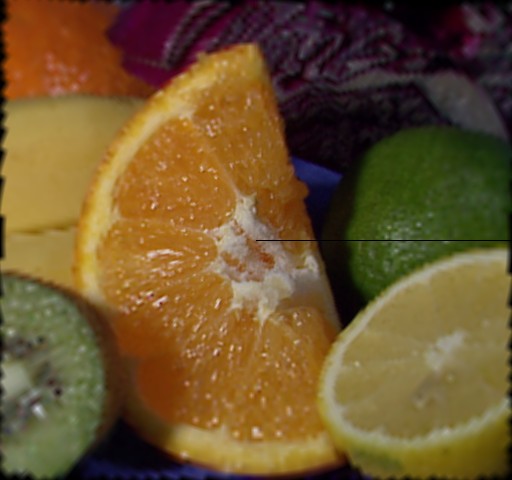
Inverse transformation ( CV_WARP_INVERSE_MAP is set):
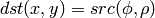
where

The function emulates the human “foveal” vision and can be used for fast scale and rotation-invariant template matching, for object tracking and so forth. The function can not operate in-place.
#include <cv.h>
#include <highgui.h>

int main(int argc, char** argv)
{
    IplImage* src;

    if( argc == 2 && (src=cvLoadImage(argv[1],1) != 0 )
    {
        IplImage* dst = cvCreateImage( cvSize(256,256), 8, 3 );
        IplImage* src2 = cvCreateImage( cvGetSize(src), 8, 3 );
        cvLogPolar( src, dst, cvPoint2D32f(src->width/2,src->height/2), 40,
        CV_INTER_LINEAR+CV_WARP_FILL_OUTLIERS );
        cvLogPolar( dst, src2, cvPoint2D32f(src->width/2,src->height/2), 40,
        CV_INTER_LINEAR+CV_WARP_FILL_OUTLIERS+CV_WARP_INVERSE_MAP );
        cvNamedWindow( "log-polar", 1 );
        cvShowImage( "log-polar", dst );
        cvNamedWindow( "inverse log-polar", 1 );
        cvShowImage( "inverse log-polar", src2 );
        cvWaitKey();
    }
    return 0;
}
And this is what the program displays when opencv/samples/c/fruits.jpg is passed to it
Remap
- void cvRemap(const CvArr* src, CvArr* dst, const CvArr* mapx, const CvArr* mapy, int flags=CV_INTER_LINEAR+CV_WARP_FILL_OUTLIERS, CvScalar fillval=cvScalarAll(0))
Applies a generic geometrical transformation to the image.
Parameters: - src – Source image
- dst – Destination image
- mapx – The map of x-coordinates (CV _ 32FC1 image)
- mapy – The map of y-coordinates (CV _ 32FC1 image)
- flags –
A combination of interpolation method and the following optional flag(s):
- CV_WARP_FILL_OUTLIERS fills all of the destination image pixels. If some of them correspond to outliers in the source image, they are set to fillval
- fillval – A value used to fill outliers
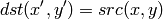
The function cvRemap transforms the source image using the specified map:

Similar to other geometrical transformations, some interpolation method (specified by user) is used to extract pixels with non-integer coordinates. Note that the function can not operate in-place.
Resize
- void cvResize(const CvArr* src, CvArr* dst, int interpolation=CV_INTER_LINEAR)
Resizes an image.
Parameters: - src – Source image
- dst – Destination image
- interpolation –
Interpolation method:
- CV_INTER_NN nearest-neigbor interpolation
- CV_INTER_LINEAR bilinear interpolation (used by default)
- CV_INTER_AREA resampling using pixel area relation. It is the preferred method for image decimation that gives moire-free results. In terms of zooming it is similar to the CV_INTER_NN method
- CV_INTER_CUBIC bicubic interpolation
The function cvResize resizes an image src so that it fits exactly into dst . If ROI is set, the function considers the ROI as supported.
WarpAffine
- void cvWarpAffine(const CvArr* src, CvArr* dst, const CvMat* mapMatrix, int flags=CV_INTER_LINEAR+CV_WARP_FILL_OUTLIERS, CvScalar fillval=cvScalarAll(0))
Applies an affine transformation to an image.
Parameters: - src – Source image
- dst – Destination image
- mapMatrix – transformation matrix
- flags –
A combination of interpolation methods and the following optional flags:
- CV_WARP_FILL_OUTLIERS fills all of the destination image pixels; if some of them correspond to outliers in the source image, they are set to fillval
- CV_WARP_INVERSE_MAP indicates that matrix is inversely
- transformed from the destination image to the source and, thus, can be used directly for pixel interpolation. Otherwise, the function finds the inverse transform from mapMatrix
- fillval – A value used to fill outliers
The function cvWarpAffine transforms the source image using the specified matrix:
where
The function is similar to GetQuadrangleSubPix but they are not exactly the same. WarpAffine requires input and output image have the same data type, has larger overhead (so it is not quite suitable for small images) and can leave part of destination image unchanged. While GetQuadrangleSubPix may extract quadrangles from 8-bit images into floating-point buffer, has smaller overhead and always changes the whole destination image content. Note that the function can not operate in-place.
To transform a sparse set of points, use the Transform function from cxcore.
WarpPerspective
- void cvWarpPerspective(const CvArr* src, CvArr* dst, const CvMat* mapMatrix, int flags=CV_INTER_LINEAR+CV_WARP_FILL_OUTLIERS, CvScalar fillval=cvScalarAll(0))
Applies a perspective transformation to an image.
Parameters: - src – Source image
- dst – Destination image
- mapMatrix – transformation matrix
- flags –
A combination of interpolation methods and the following optional flags:
- CV_WARP_FILL_OUTLIERS fills all of the destination image pixels; if some of them correspond to outliers in the source image, they are set to fillval
- CV_WARP_INVERSE_MAP indicates that matrix is inversely transformed from the destination image to the source and, thus, can be used directly for pixel interpolation. Otherwise, the function finds the inverse transform from mapMatrix
- fillval – A value used to fill outliers
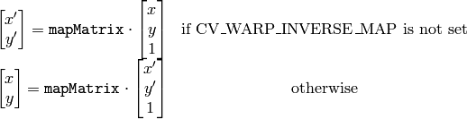
The function cvWarpPerspective transforms the source image using the specified matrix:
Note that the function can not operate in-place. For a sparse set of points use the PerspectiveTransform function from CxCore.
Help and Feedback
You did not find what you were looking for?- Ask a question in the user group/mailing list.
- If you think something is missing or wrong in the documentation, please file a bug report.